When you press the power button on your desktop, the signal is transmitted through the Power Switch cable to the mainboard. It is one type of Front Panel cable. Let’s learn more about it!
1. Front Panel cables
– Location: located on the inside front panel of the PC case.
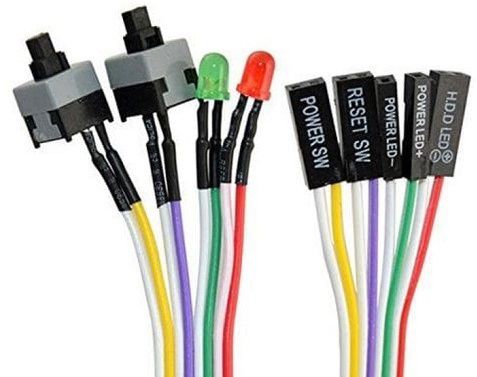
– Function: connect the power button, reset button, hard drive light, and power light to the mainboard.
– There are 4 types: Power Switch, Reset Switch, HDD Led, and Power Led.
– Functions of different types of signal wires:
- HDD Led: signal cable for hard drive light
- Power Led: signal cable for the mainboard power light
- Power Switch: signal cable to connect the power button
- Reset Switch: signal cable to connect reset button
2. Front Panel connectors on the mainboard
To connect the front panel cables to the mainboard, simply plug them into the front panel connectors on the mainboard.
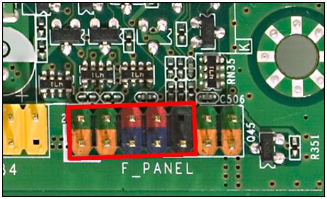
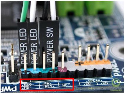
– Front Panel connectors on the mainboard include 9 pins with labels such as FP, FP_1, F_PANEL, and JFP.
– At the bottom of the front panel connectors, you’ll see symbols like +MSG-, +HD-, +PW-, -RES+, NC (No Connection) or +PWR_LED-, +HDD_LED-, PWR_SW, RESET.
3. How to connect front panel cables to the mainboard?
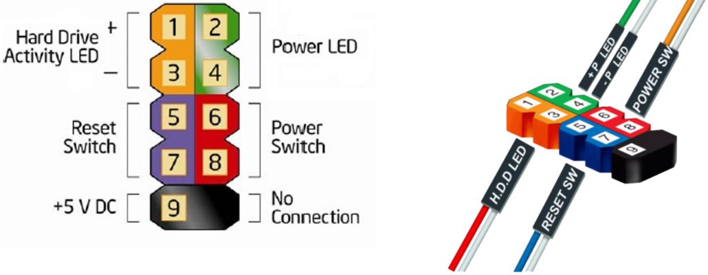
To connect the cables, attach pin 1 and 3 to the HDD LED, pin 2 and 4 to the Power LED, pin 5 and 7 to the Reset Switch, and pin 6 and 8 to the Power Switch.
Notes for plugging in Front Panel Cables to Front Panel Connectors
- To connect the led cables (HDD led, power led), make sure to plug them into the correct + and – pins. The + pin of the signal cable is usually a pin with a prominent color such as green, red, etc.
- The Reset Switch and Power Switch cables do not require attention to the + and – pins, but they must be mounted in the correct location on the Front Panel.


