1. Lesson objectives
- Introduction to desktop cables, including front panel, audio and USB cables, and data cables.
- Properly disassemble front panel cables, audio and USB signal cables, and data cables.
2. Instruments preparation
Each student prepares the following tools:
Main tools:
- 01 Desktop computer
- 01 screwdriver
- 01 screw box
Support tools:
- 01 computer cleaning brush
- 01 cleaning cloth
3. Front Panel cables
The Front Panel cables are inside the front of the case. They connect the Power Switch, Reset Switch, HDD Led, and Power Led to the mainboard.
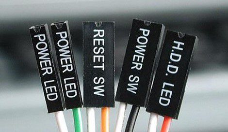
The colors of the Front Panel cables can vary depending on the manufacturer, but they are labeled clearly on the wires themselves. For example, the Front Panel cables in the image above will have the following colors:
- Power SW: black-white
- Reset SW: orange-white
- HDD LED: red-white
- Power LED: green-white
The Front Panel cables will be connected to the Front Panel connectors on the mainboard. The mainboard’s Front Panel connectors consist of 9 pins, typically labeled as FP, FP_1, F_PANEL, and JFP.
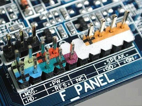
The front panel connectors have symbols like +MSG-, +HD-, +PW-, -RES+, NC (No Connection), or +PWR_LED-, +HDD_LED-, PWR_SW, RESET. Refer to the picture below to correctly plug the front panel cables into the front panel connectors.
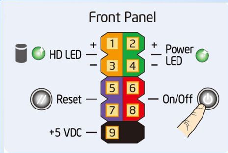
Notes for plugging in Front Panel Cables to Front Panel Connectors
- To connect the led cables (HDD led, power led), make sure to plug them into the correct + and – pins. The + pin of the signal cable is usually a pin with a prominent color such as green, red, etc.
- The Reset Switch and Power Switch cables do not require attention to the + and – pins, but they must be mounted in the correct location on the Front Panel.
4. Audio, USB, and Speaker cables
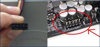
Audio cable
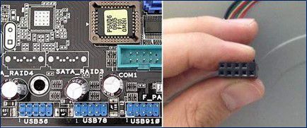
This cable transmits signals between the audio port and mainboard and is located on the inside front of the case. The mainboard’s audio connector and audio cable will also be missing an 8th pin.
USB cable
The USB cable connects the USB port on the front of the case to the mainboard. It’s important to note that both the USB connector and the USB cable will have a missing 9th pin.
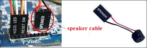
Speaker cable
The speaker can help check if the RAM or CPU is faulty during startup by emitting beep sounds. Usually, the speaker connector has 4 pins located next to the Front Panel connector and when plugging in the speaker cable, there is no distinction between negative or positive polarity.
5. Data cables
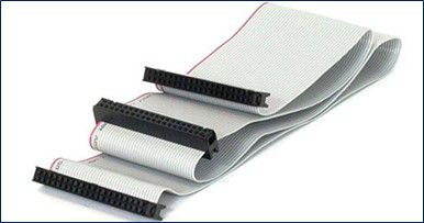
ATA cable
An ATA cable connects storage devices to the mainboard with an ATA standard physical interface. The connectors on an ATA cable have 40 or 44 pins.
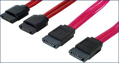
SATA cable
Serial ATA (SATA) is a standard physical interface that replaces ATA. SATA has a transfer speed of 150MB/s or 300 MB/s, whereas ATA has a maximum speed of 133 MB/s.
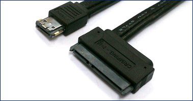
eSATA cable
eSATA (external Serial Advanced Technology Attachment) is a version of the SATA that connects with external hard drives, providing a data transmission speed of 3 Gbit/s, which is the same as a SATA cable.
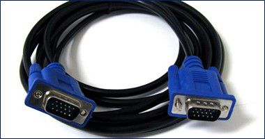
VGA cable
VGA (Video Graphics Array) is a standard physical interface for connecting to a monitor. A VGA cable has 15 pins that are plugged into 3 rows, with each row having 5 pins.
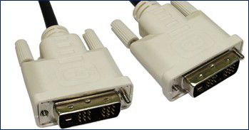
DVI cable
DVI (Digital Visual Interface) is a standard physical interface used to transfer digital video content. This cable can transmit high-definition (HD) video with a maximum resolution of 1920×1200. Dual-link DVI cables support video with a maximum resolution of 2560×1600.
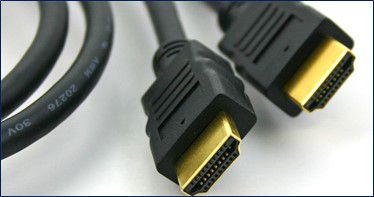
HDMI cable
HDMI (High-Definition Multimedia Interface) is a standard physical interface that transmits images and sounds through a cable to a large projection screen such as a television while ensuring high resolution.
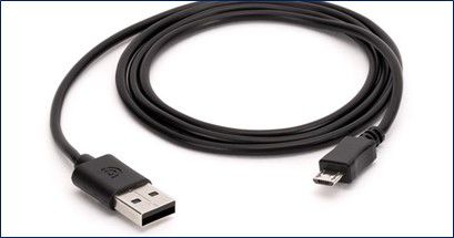
USB cable
USB is currently the most widely used type of connection in the world. A wide range of peripheral devices, including keyboards, mouse, and external storage drives, can be connected to a computer via USB. There are different versions of USB, including USB 1.0/1.1, USB 2.0, and USB 3.0, as well as variants like mini USB and micro USB.
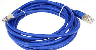
Ethernet cable
Ethernet cables are used for setting up local networks. They commonly connect network devices to each other or to computers.
6. Requirement of practice
- Every student will receive practical tools.
- Disassemble and assemble the Desktop computer step by step and follow the regulations.
- Identify and correctly disassemble Front Panel cables and data cables.
- Complete the practice sheet for lesson 03.
- You are required to take pictures and record videos for documentation.
7. Practice sheet
Each student downloads the practice sheet here, photographs it, and brings it along when practicing.